


Principles of Automobile Instrument
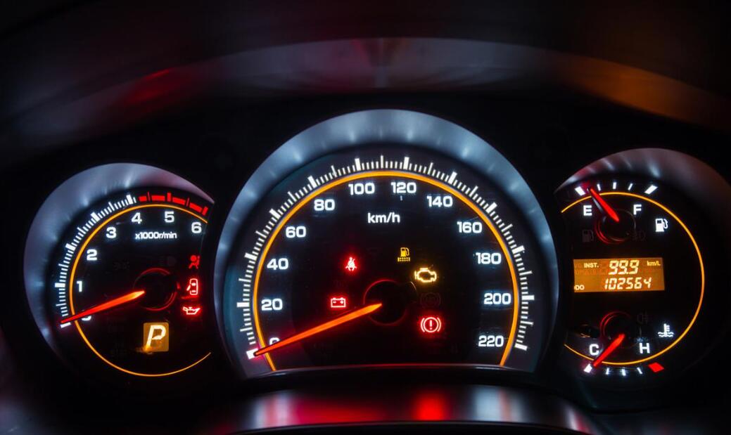
Speedometer
The traditional speedometer is mechanical. A typical mechanical odometer is connected to a flexible shaft. There is a cable inside the flexible shaft. The other end of the flexible shaft is connected to the gear of the transmission. The gear rotation drives the wire rope rotation. The cable drives the magnet in the odometer cover ring to rotate. The cover ring is connected with the pointer, and the pointer is placed at the zero position through the hairspring. The rotation speed of the magnet causes the change of the magnetic line of force, the balance is broken, and the pointer is driven. The speedometer is simple and practical, and is widely used in large and small cars. However, with the development of electronic technology, many automotive instruments have used electronic speedometers. A common method is to obtain the signal from the speed sensor on the transmission and deflect the pointer or display the number through the change of pulse frequency.
Odometer
The odometer is a digital instrument. It engages with the worm on the speedometer transmission shaft through the transmission gear of the counter drum to make the counter drum rotate. Its feature is that the upper drum rotates one full circle and the lower drum rotates 1/10 circle. Like the speedometer, the odometer also has an electronic odometer, which obtains the mileage signal from the speed sensor. The mileage accumulated by the electronic odometer is stored in the non-volatile memory, and the data can also be saved without power.
Tachograph
Another more conspicuous instrument is the tachometer. Tachometer in 1/min × 1000, which is how many revolutions the engine rotates per minute. The tachometer can visually display the engine speed under various working conditions. The driver can know the operation of the engine at any time, cooperate with the transmission gear and throttle position to keep it in the best working state, which is conducive to reducing fuel consumption and extending engine life.
The tachometer is generally set on the instrument panel and placed symmetrically with the speedometer. The tachometer works according to the principle of magnetism. It receives the pulse signal generated when the primary current in the ignition coil is interrupted, and converts the signal into a speed value that can be displayed. The faster the engine speed, the more pulses generated by the ignition coil, and the greater the speed value displayed on the table.
Generally, cars are electronic tachometers, including pointer type and LCD digital display type. There are digital integrated circuits in the instrument. It drives the pointer to move or digital display after calculating the voltage pulse transmitted from the ignition coil. In addition, there is a tachometer, which receives the pulse signal from the generator and sends it to the tachometer circuit for interpretation, and then displays the speed value. However, due to factors such as slipping of generator belt, this value is not accurate.
The oil pressure gauge, water temperature gauge and fuel gauge on the instrument panel are directly related to the operation of the engine. Each has its own sensor to reflect the information of the monitored object on the instrument.
Oil pressure gauge
The oil pressure gauge is an instrument that displays the oil pressure in kPa (kPa). The oil pressure gauge sensor is a piezoresistive sensor, which is connected to the engine oil pipeline through a fixed thread. The oil pressure pushes the contact plate to move on the resistance, thus changing the resistance value, thus affecting the amount of current passing through the instrument to the ground, thus driving the pointer to swing. Because the oil pressure has a certain pressure range, for the sake of clarity, many automobile oil pressure gauges are indicated by indicator lights. If the light is still on when the engine is running, it indicates that the engine lubrication system may be abnormal.
Water temperature gauge
The water temperature gauge is an instrument that displays the temperature of cooling water, with the unit of ℃ (Celsius). Its sensor is a thermistor type sensor, which is fixed on the engine cooling water channel with threads. The thermistor determines the current flowing through the coil winding of the water temperature meter, thus driving the pointer of the water temperature meter to swing. In the past, the cooling water of automobile engines was used as tap water. Many automotive engine cooling systems use special coolant, so they are also called coolant thermometers.
Fuel gauge
The fuel gauge is an instrument that shows the amount of fuel in the tank, in L (liter). Pointing to "F" indicates full oil, and pointing to "E" indicates no oil; 1/1, 1/2 and 0 are also used to indicate full oil, half tank oil and no oil. There are two coils in the fuel gauge, which are located on the "F" and "E" sides respectively. The sensor is a variable resistor controlled by the floating height. The change of resistance value determines the magnetic line strength of the two coils, and also determines the deflection direction of the pointer.
Water temperature gauge and fuel gauge
The water temperature gauge and the fuel gauge are also indicated by the indicator lamp. When the water temperature indicator is on, it means that the water temperature is high, and when the fuel indicator is on, it means that the fuel is close to the low point, as an auxiliary reminder.
Charge meter
The charging meter shows the charging and discharging status between the generator and the battery, which can be divided into ammeter and voltmeter. In the past, most cars used ammeters. It has a permanent magnet to fix the pointer in the middle of the fulcrum. There is a coil around the fulcrum. When a current flows through the coil, it will induce a magnetic field. The pointer swings left and right under the action of magnetic field. The direction of swing depends on the direction of current flowing through the coil. Therefore, the ammeter is connected in series between the battery and the generator. When the generator is charging the battery, the instrument displays positive (+). If the discharge capacity of the battery to the load is greater than the charging capacity of the generator, the instrument displays negative (-). Because the ammeter terminal bears relatively large current, it is not safe. When the engine is running, the grounding wire of the charging lamp is connected and the charging lamp is on; When the engine is not running, the grounding circuit of the charging lamp is disconnected and the charging lamp is off; If the charging lamp is still on, there is a fault in the charging system.